Note from the editor: This page was entirely written by John S from Tabard RFC, who not only adapted the design and software for Rugby Football, but he also built his own scoreboard and even wrote up his own build summary which saved me hours of time. I have edited the contents slightly to fit in with slight flow, but all words are from John! Congratulations John and Sam, what an amazing build and another brilliant contribution to the project! Westbury on Severn RFC…. have you seen this? Is it time to update that manual scoreboard?
The Tabard RFC scoreboard is based on the Westbury on Severn cricket Club scoreboard project which can be found at https://buildyourownscoreboard.wordpress.com/ Tabard owe a massive debt of thanks to Westbury for the detailed information on this website and especially to Ian N who provided email assistance whenever we were struggling. Thank you Ian without your help this project would never have reached completion!
The scoreboard was built by John Strickland at Tabard RFC who started the project in November 2016 with the design and programming of the scoreboard and it’s user interface. Things progressed well with the software and even with the electronics despite John having absolutely no experience with electronics. The build of the physical board progressed far slower with John looking at several different approaches for the actual digits. The breakthrough came when Sam Musk (Many thanks Sam!) agreed to give his time and expertise in laser cutting the digits and lenses.
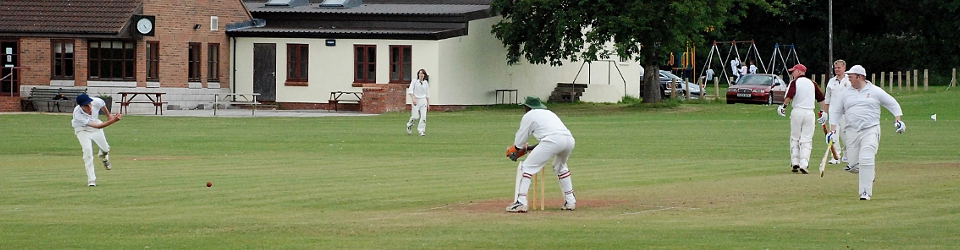
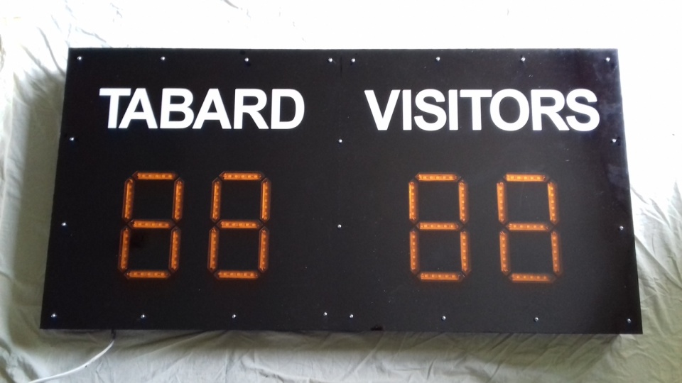
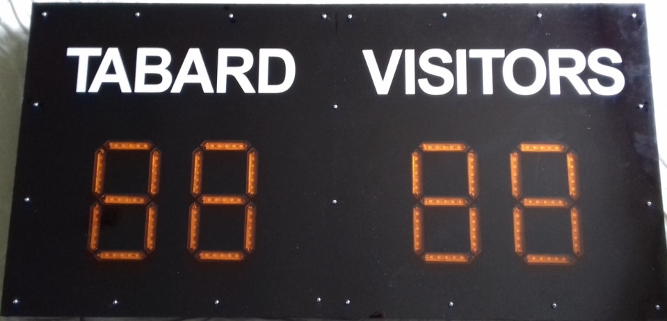
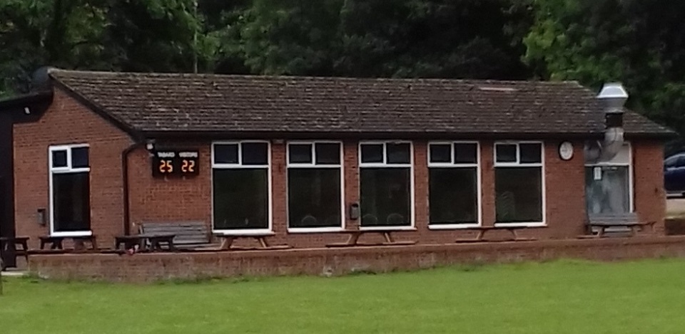
The final Tabard RFC scoreboard is shown below prior to being installed on the clubhouse wall facing the First XV pitch. It was finally installed in August 2017 in time for the 2017/18 season.


As with other builds the board is difficult to see when close up but from a distance the numbers are very clear.
Building the circuit.
Tabard RFC did not use the Westbury stripboard approach but instead used the following 91x45mm Copper Prototype PCB Stripboard/ Printed Circuit Board/Strip/Vero Board available from ebay (Just search on the description) which removes the need for cutting/drilling of the stripboard
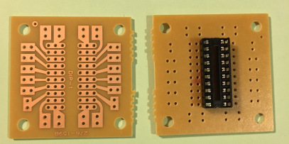
Insert the IC DIP20 module on to the board, with the pins at the top (by the u shaped semi circle) as shown in the picture above. Solder the DIP20 on to the board. Soldering is fiddly but is probably easier than you think!
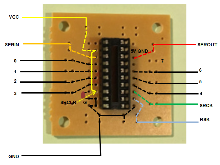
Add the capacitor to the circuit board. It should be between the SRCLR and G strips. Bend the pins so they touch the copper strips and solder them on. Now add a short length of yellow wiring between the VCC input and the SRCLR input and also add two short lengths of black wire to link the ground connections(see circuit layout above).
Now add lengths of cable of around 20 cm to each of the legs of the DIP20 socket, and solder them in (using the diagram above). Once all of the soldering is done, you can insert the Shifter IC in to the DIP20 socket (make sure the U shape on top of the IC is inserted in to the same end as the U shape on the DIP20 socket).
it is very sensible to label each of the cables with a piece of masking tape, it really helps when you test.
Do this just 4 times for the rugby scoreboard and you are done!
Setting up the Arduino, Raspberry and wireless controller
Follow the normal instructions from the buildyourownscoreboard.wordpress.com site, and make sure you test using the instructions supplied.
Setting up the Tabard RFC interface
John Strickland at Tabard RFC re-wrote the web interface for a Rugby Club based on that written by Chris at Bradford upon Avon CC. However, before you install the interface please make sure that you have setup and tested the standard Westbury on Severn interface fully (with a set of LEDs), before you attempt an upgrade. This makes troubleshooting so much easier.
Tabard software is available from the download page (thanks to John for sharing) or from here.
Tabard Rugby Football Club Scoreboard – Software changes
The Tabard rugby scoreboard interface is modelled on the Bradford upon Avon CC version but built to accept changes to Tries, Conversions, Penalties and Drop Goals. The only information displayed on the physical scoreboard is the total score for each team and we only allow two digits for each team (A score of more than 99 for an individual team is so rare we decided that we would not cater for it).
We expect that the scoreboard will be updated by a supporter from the touchline and thus the interface has been designed to operate on a smartphone with reasonable sized screen. The interface will also operate from tablets or laptops and will adapt dependent on the screen being used.
The scoreboard will be mounted on the external clubhouse wall and thus should be visible from most positions along the touchline. In bad weather some supporters watch from inside the clubhouse and will be unable to view the scoreboard. We have therefore provided a second html screen which will allow supporters to check the current score on their smartphones.
The following changes were made to the standard Westbury on Severn software which we used for our initial testing of circuits.
(1) Scoreboard Interface – Web pages
Index.html – Scorer’s screen (This must replace the original in the folder /var/www/html/css/ on the Pi).
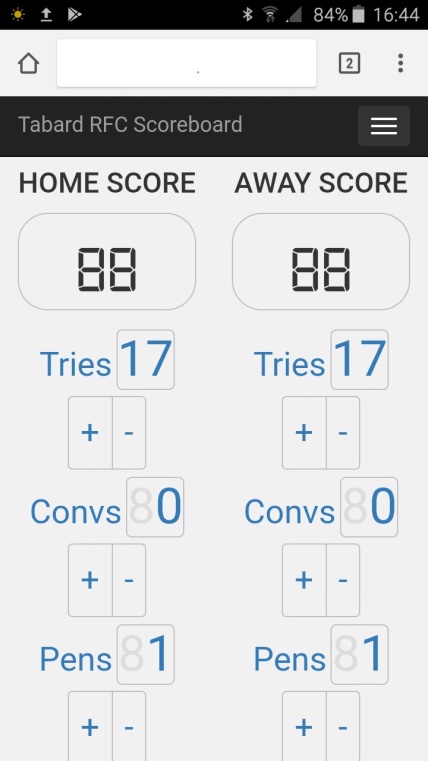
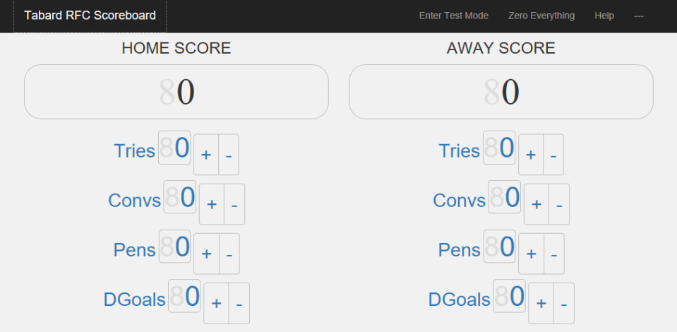
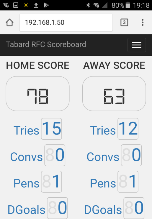
This screen is shown below(Smartphone and Tablet/Laptop versions) and allows changes to be made to number of Tries(5 pts), Conversions(2 pts), Penalties(3 pts) and Drop Goals(3 pts). The screen script then updates the teams scores by adding the appropriate values. The scorer’s screen is updated immediately and the physical scoreboard is updated after a delay of just 5 seconds which should be sufficient for the scorer to spot and correct any error of input.
Smartphone version (Note: we have to scroll to reach Drop Goal information)

Tablet/Laptop version
Score.html – Supporter’s screen (This must be placed into the folder /var/www/html/css/ on the Pi).
This smartphone version of this screen is shown below. The supporter obtains the current scores by selecting the Menu (3 horizontal bars) and then pressing on the “Load latest score” button. Note that the supporter’s screen shows the full details of the scores with counts of Tries, Conversions, Penalties and Drop Goals.
There is also a second version of this screen which automatically loads the current score every 15 seconds (Scoreauto.html). At Tabard we have used the auto update version and set is as index.html so that it is the default screen on entry to the website. We have moved the scorer’s screen elsewhere and renamed it for security.
(2) CSS changes
To support the smartphone interface we amended the css file 3-col-portfolio.css which must be placed in the folder /var/www/html/css/ on the Pi.
(3) Information stored in the save.txt file
In our version of the scoreboard software the save.txt file holds the total scores for each team together with the detailed breakdown of tries, conversions, etc. To support this changes were made to the Scoreboard.php file. screen (This file must be placed into the folder /var/www/html/ on the Pi).
(4) Arduino software
The Arduino sketch file scoreboard.ino file was amended to just display two digit totals score for each team.
When you come to amend your system to use the Tabard interface you must use this file to replace the original scoreboard.ino file as described in the Setting up the Arduino section of the main setup documentation.
Please note that we switched to using pins 5, 6 & 7 on the Arduino following a suspected short on pins 2, 3 & 4 which appeared to give us unpredictable results. Anyone using our software can still wire up the Arduino using pins 2, 3 & 4 but the scoreboard.ino file must be changed to reflect this.
(5) Script changes (In folder js)
The javascript file SendToArduino.js was changed to send just two digit home score and two digit away score. The javascript file testing.js was changed to run a simpler test sequence.
This now simply cycles through the numbers 0, 11, 22, 33, 44, 55, 66, 77, 88, 99 for both teams and the returns to display the scores held in save.txt. Note: 00 is displayed as just one zero, in the second digit position.
These files must replace the originals in the folder /var/www/html/js/ on the Pi.
Once the test displays have finished the scoreboard returns to display the current score using the contents of the file save.txt
The physical scoreboard is shown below
How to update the Arduino with the new scoreboard.ino file
Unzip the TabardScoreboard.zip file on your PC and then use the scoreboard.ino file contained within to update the Arduino as described in the Setting up the Arduino section earlier in this document. The ino file provided uses pins 5,6 & 7 it is probably simplest if you edit this to use pins 2,3 & 4 otherwise you will need to rewire the Arduino connections to use pins 5, 6 & 7.
Update the software held on the Pi.
You now have two clear alternatives:
- Load the complete set of software from “TabardScoreboard.zip”
- Extract just the amended files (As documented in “Scoreboard Software changes.docx”) and load them into the appropriate folders in /var/www/html/. ( I prefer this alternative).
Load the complete set of software from “TabardScoreboard.zip”
Now download the TabardScoreboard.zip file to the /home/pi/tabard directory on the Raspberry using WinSCP (you will have to create the tabard directory using WinSCP).
To install the interface, we should start by making a backup copy of the original Westbury on Severn interface and then deleting it from the apache directory. To do this open a terminal on the raspberry and run the following commands (with significant care!)
sudo cp -r /var/www/html /var/www/html.old
sudo rm -rf /var/www/html/*
Now open a terminal on the Raspberry, and unzip the files with the following command
cd /home/pi/tabard
unzip TabardScoreboard.zip
Now copy the files from the tabard directory into the apache directory and set the correct permissions with the following commands:
cd /home/pi/tabard/
sudo cp -r * /var/www/html/
sudo chown -R www-data: /var/www/html/
sudo chmod 666 /var/www/html/save.txt
Alternative – Extract just the amended files (As documented in “Scoreboard Software changes.docx”) and load them into the appropriate folders in /var/www/html/.
On your local PC unzip TabardScoreboard.zip and go to directory “Scoreboard Changes” which should look like the following
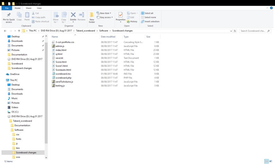
Now transfer all the Software Changes files into the PI home directory using WinSCP and then open a terminal on the Pi and copy the individual files into their correct directories.
Whichever method(1 or 2 above) you’ve used now edit the admin password that is required to shutdown or reboot the board by editing the /var/www/html/veriifyadmin.php file. Update the if($_GET[‘pass’]==”admin”) line to change the password from admin to something secret.
Now we can test the software is working correctly. First, open a terminal and run (this will sit in an endless loop):
sudo /usr/local/bin/scoreboard/readFromSerial.sh
Leave that terminal open, and now open a second terminal and run:
sudo tail -f /var/log/scoreboard.log
Now using a browser, open the scoreboard web interface from your laptop. I recommend using Chrome for this. Type in the name of the IP address of the Raspberry in to the address bar and the interface should load. Change the score.
In the second terminal you opened you should see something like the following (but with tries,conversions, penalties and drop goals) :
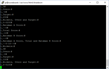
If this is displayed, and the interface has loaded correctly. then the task is complete!
Building the board
Full instructions on how to layout (and cut-out) the board are available from the pdf file here.
The final Tabard rugby scoreboard is shown below prior to being installed on the clubhouse wall facing the First XV pitch.
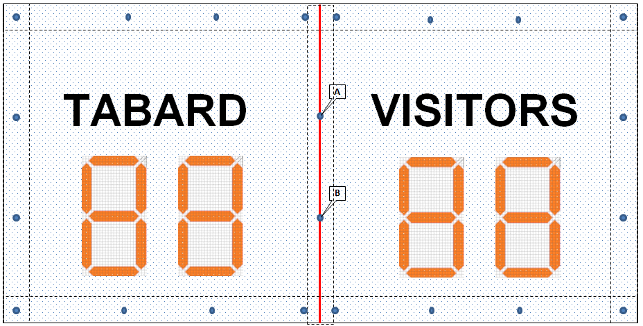
Scoreboard Design (610mm x 1210mm)
The scoreboard is built on a frame of 4 x 2 inch timber battens to which 6 mm marine plywood is attached back and front(4” provides depth for the electrics). The front plywood has holes cut for the lamps which are marginally larger than the lamps and marginally smaller than the lenses and thus hold them onto the black acrylic(3 mm) sheets which form the next layer.
All plywood and timber battens were given at least two coats of black paint before beginning assembly. We bought weathershield black silk, which can be used as an undercoat as well. Spend time sealing the edges of the board as these will be exposed to the weather.
Assemble the 4” x 2” framework first and then attach the front plywood section(with lamp cutouts).
The lamps are glued to short strips of MFA Perforated Metal Strips (available from Maplins) and screwed on to the plywood.
The black acrylic was ordered as two equal sized sheets (610 x 605 mm) since the laser cutter used to cut the digits could not hold the full sized sheet. We owe a big thank you to Sam Musk who provided the expertise necessary to cut the digits into the black acrylic and cut the amber “lenses” from two A4 sheets of amber acrylic.
The amber lamp “lenses” sections are cut to exactly fit the laser cut holes in the black acrylic sheets (3 mm) and simply press into place before the black acrylic sheets form the next layer.
Stick the vinyl lettering onto the black acrylic sheets.
Overlay the black acrylic sheets with the single clear acrylic sheet(3 mm) to provide a protective waterproof covering and hold the front of the lamp “lenses” in place. The acrylic sheets are held in place by screws as indicated by the blue dots (Approximate spacing between screws is 8”). Use a metal drill to drill through the acrylic sheets and set the drill on the slowest speed. When you screw in the screws use a washer between the screwhead and the acrylic to prevent cracking. Screws A and B will breach the edges of both black cutout sheets but this edge will be held in place by the clear acrylic sheet. The red line denotes the separation of the two sheets of black acrylic
Note: Clear the clear acrylic sheet is available in this size but the plywood will need to be cut down from 610×1220 mm.
All electronic/electrical components are wired up and attached to the plywood and framework at this point using the wiring diagram from the “build the circuit” page. Note that the digits are wired from left to right (as you look from the front) this is reversed when you look at the rear of the board.
The wiring order, from the front, should be:
HomeScoreTens, HomeScoreOnes, AwayScoreTens, AwayScoreOnes
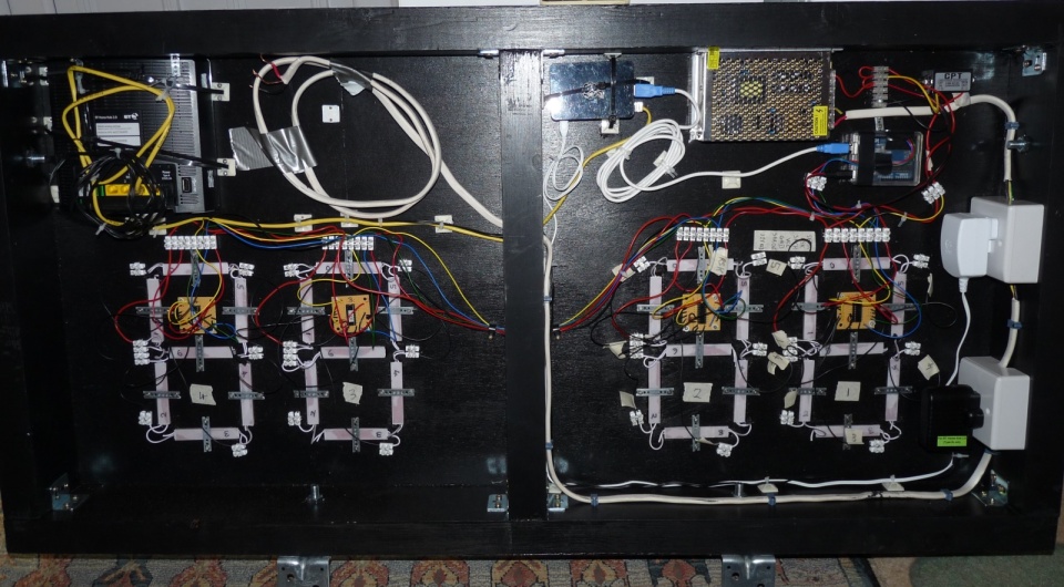
IMPORTANT NOTE: It is important that at this stage you have your wiring checked by a qualified electrician before you plug the power supply in to mains power. Keep everyone safe, by preventing electrical shock and fire!
Once wired up, give it a test!
Before attaching the back, use some black silicon to seal up the top third of the board to keep the water out of the electrics. Our scoreboard is mounted on the clubhouse wall and protected from the elements to some degree by the overhanging roof.
The finished article
The user interface


How the scoreboard looks
Not as impressive as the cricket scoreboards [ed: rubbish, it is amazing!] with their mass of digits but it is legible from the far end of the rugby pitch.
